
From April 1994 to May 1995 I was a Light Infantry Rifle Platoon Leader in the United States Army. As a new Lieutenant, I was often overwhelmed with the amount of information I needed to track. Since then, I’ve made a career of building systems to track information. The tool I use to model software before I write it is called the Unified Modeling Language, or UML. I’ve long though about the structure of the information from my time in the Army. Here’s a start at modeling the information a new Platoon Leader needs to track.
Before I start, I’d like to state that I am not writing the specification for software, the schema for a database, or even any automated systems. This is information modeling. It could be used to build automated systems, but it should be useful in its own right.
The first question we ask when designing a new system is: what are we trying to accomplish. The standard UML tool for displaying this information is called a use case diagram. While use case documents can be extremely detailed, a use case diagram is more of an overall map to the application or domain of knowledge. Below is the start of a use case diagram for a platoon leader or platoon level Non-commissioned Officer (NCO).
- Leadership Use Cases
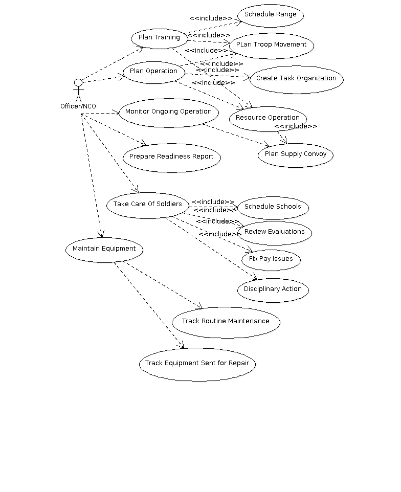
The use cases go from general to specific, and show that there are some tasks that are common for larger tasks. For instance, the use case plan troop movement is part of several other larger things that a PL has to do.
Most end user software applications, especially those targeted at multiple users, are built on a design pattern referred to as Model-View-Controller or MVC for short. The idea is that the application has a model of the information it manages, and the end use sees a view of that. Changes to the view are sent to a controller that enforces the constraints of the system, updates the model, and notifies the other views that the model has changed. IN the Army, the view is Paperwork. Even if the documents are all controlled electronically, when we say paperwork, people know what we are talking about.
Here is a small slice of the views that a platoon leader needs to understand:
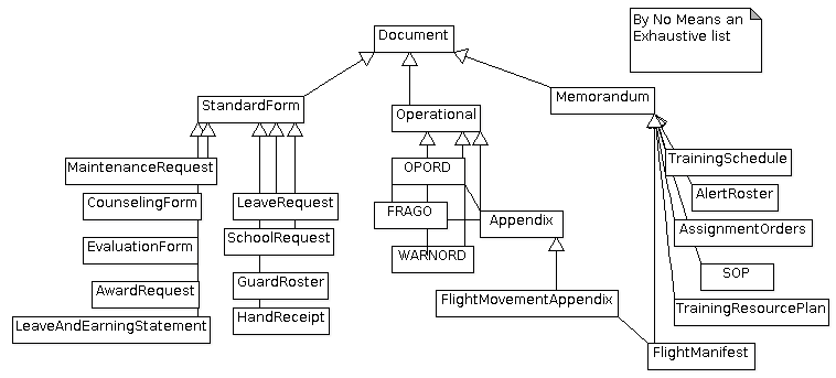
A comment on notation: the open triangle represents a special kind of relationship: is a. IN object oriented programming, this typically means inheritance. In databases or a procedural language like C…it is more complicated, but in all cases there is an intention of joining data of a general type to a variety of more specific instances.
The controller in this system is the system of soldiers that move the paperwork around: pretty much everyone. Yep, we are all really just one big computer.
Now that we some idea of what we are trying to accomplish, the next question we have to answer is: what is the information we need to track? In UML, the structure of the data is displayed in a class diagram. For database folks, this is very similar to an entity-relationship diagram. Now, when people new to programming or information modeling first tackle a task like this, they tend to clump things together that are related, but different. For example, A person may have multiple telephone numbers. A new modeler might try to define the telephone number as an attribute of a person, but they are really different attributes. The act of splitting out these attributes is called normalization. The model I have here is very normalized, perhaps overly so, but I find that in a domain model it is better to split things into as fine a detail as possible, and then in code you can de-normalize if necessary.
This is getting to the heart of the information modeling. Let me reiterate that this is not code. Instead, this is a domain model. It is a tool for communication. During Vietnam, Korea, WWII, and earlier, before computers were commonplace, this same information was tracked, but on pieces of paper. Data from each entity might be duplicated on multiple pieces of paper, and sometimes they would conflict due to typos. But they were all an attempt to record this abstract model of the information necessary to keep the Army Rolling Along.
Here’s my domain model.
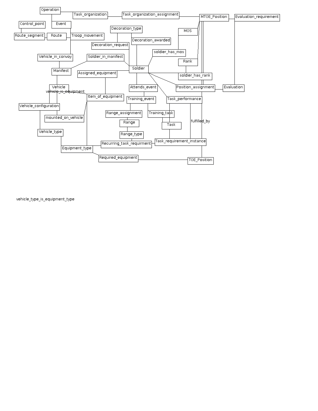
As a wise old NCO once said: “Let me orientate you to my range!” The heart of the domain model is the Soldier. However, we attempt to remove as much information from the core Soldier object as possible, leaving perhaps only a unique Identifier (possibly based on SSN, but beware of the risks involved with identity theft) name, and date of birth. Much of the other information about a soldier is extracted out into other entities and then captured in assignment relationships. A good rule of thumb is “don’t delete information.” If a particular piece of information changes over time, add a new record each time it changes, and then select the latest one. For example, you want to keep track of a soldier’s rank. The simplistic implementation is to have date of rank and rank fields on the Soldier object. But Rank is a Stand alone entity. For example, each rank has both a shorthand and full description: O1 and Second Lieutenant. In the Navy, O1 is Ensign. Yes, we probably shouldn’t call the table Soldier, but instead “service member” but we have to draw the line somewhere, and I draw it at the Navy. The relationship “soldier_has_rank” could be called “promotions_and_demotions” as well, and would indicate both the rank attained and the date it was attained. The same goes for MOS.
Many things in the Army have a “power type”. For example, a vehicle can be a HMMWV Truck, an M1 Abrams Tank, or a UH-60 Helicopter. Instead of recording the capacity on each vehicle, you get generalized information like this out of the _type entities. For vehicles, we can go even further, as they have multiple standard configurations, and capacity might be determined in a a Black Hawk based on what configuration it is set up in for a given mission.
Lets look at the subset of classes that are used in a common leader task: generate a manifest for an aircraft movement.

These are the pieces that you need to fit together to make a flight manifest. What this model does not show is the wisdom required to make a sensible manifest, but that is what experienced NCOs are for: wisdom. One of the rules of thumb, though, is that you try to keep a chain of command intact while packing people into these aircraft. Let me show you how tricky this can be.

This is an instance diagram. Usually, with UML, I prefer to show these with rounded corners, to distinguish them from classes. But each rectangle here represents a single Datum: in database speak, a single row. I’ve made a few concessions to legibility (and time constraints) most notably that I put the rank on each of the Soldiers. I don’t specify the MTOE positions, but they would have fields such as Rifleman, Grenadier, SAW Guner ,Team Leader, M60 Gunner, Assistant Gunner and Squad leader. The arrows between MTOE position instances show the chain of command. Our Chalk leader is SSG Kowalski, in the middle. He has two of his fire teams with him, headed by SGT Slaughter and SGT Corrales. Additionally, this manifest has one M60 team, lead by SPC Gurnsey, as well as a fire team from a different squad, lead by SGT Adams. This manifest is for a UH 60 in the configuration that allows 15 grunts, ready for a long patrol.
This is the start of the conversation, and it has a long way to go. The domain model needs much more detail. Each entity is really a collection of fields, and those fields need to be defined. There are many more use cases than are enumerated here, and each case can have many variations. Certain things which are identified as singe entities may not work that way in practice: the requirements for APFT and Rifle marksmanship, while both regularly occurring are recorded and calculated very differently. But perhaps the true value in a model like this is in the modeling, helping the people that use it understand their domain better.
To those that are interested in continuing the conversation: I used ArgoUML to draw the diagrams. It is a Java based tool that you should be able to run directly from your browser. The tool is here: I’ve made a GIT repository with the project model is here. https://github.com/admiyo/PlatoonUML